Page was created: 10.02.05
Page was last updated: 10.02.05
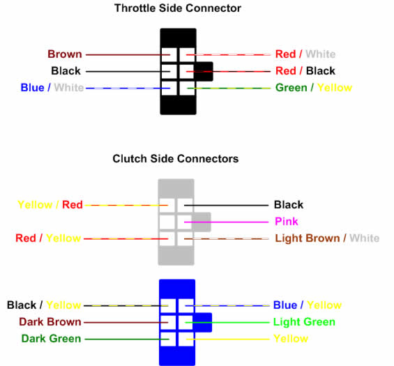
Under the tank you will find the end of the wiring harness. Disconnect the connectors. At this point you will need to get a piece of paper and sketch the open end of the connector. Color code each pin position of the harness. It is very important that you get your wiring diagram/schematic coded correctly.
The connector ends come off of the wiring harness with the use of a small flat head screwdriver (jewelers screwdriver). If you look at the connector (opposite where the wires go in) you will see the wire termination. This has a small tang that you will depress with the small screwdriver. The wire will fall out of the connector. Make sure that you draw the wiring diagram/schematic of the connector end and the wire colors prior to removing the wires!
I used the vacuum method with dental floss that was doubled up and taped to a single pull wire, then the pull wire to the bundle. Place a vacuum at the bottom of the risers where the harness exit hole is and then feed the dental floss at the other end. Then pull the dental floss through to get the feed wire out. Gently pull on the feed wire to get the harness through the bars. Take your time and you may have to do a pulling back and forth type of action to get the harness to make the transition from the bar to risers. The left side is tighter to feed than the right, but it will go through. There is some electrician lube that is available at the hardware store that will help ease pulling the harness through.
On the left side you will need to install the mirror mount prior to feeding the bundle. Feed the bundle through the left mirror mount and then through the hole.
I drilled two 3/8" holes on the top triple tree, just on the inside of the riser mounting holes, to feed the wires through. The triple tree is aluminum so it drills through very easily.
I re-used the stock grey vinyl sleeve from the wiring harness to cover the harness exiting the risers going through the triple trees. It's almost invisible. Under the triple tree I combined the two sides and covered them with black corrugated wire tubing since that's what I had in the garage.
I fed the entire wire bundle to the left side neck cover and re-attached the appropriate wires to the connectors using the wiring diagram/schematic that was created before everything was taken apart. Then just plug the connectors to the mating connectors. Before buttoning up everything. Turn the ignition to the on position and verify that your turn signals, horn, high beam, and kill switch works. If everything checks out then reattach the neck cover and re-install your tank.
Also reference pictures at www.650ccnd.com/wire.htm
Wiring diagram borrowed from Dustin at www.650ccnd.com/wire.htm